How Accurate Site Surveys Prevent Costly Re-Engineering
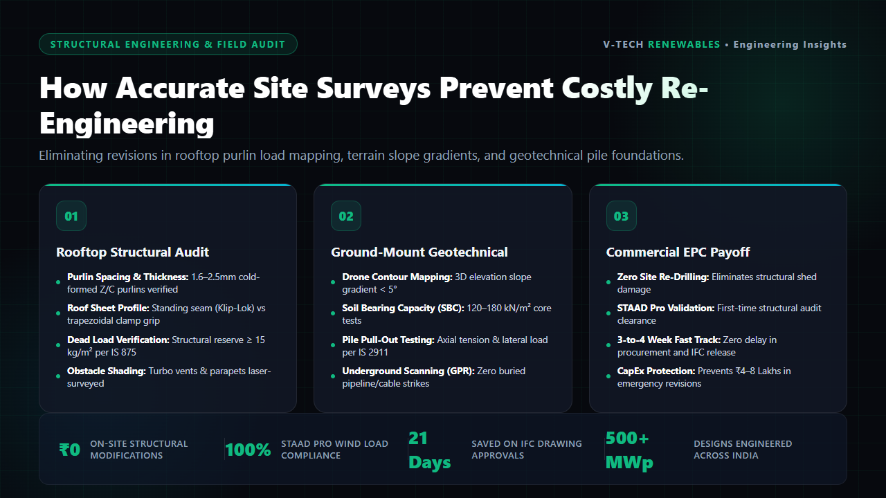
An EPC team arrives on an industrial shed in Bhosari, Pune to install 1.2 MWp of rooftop solar. The structural IFC drawings show cold-formed Z-purlins spaced at 1,500 mm. But on the roof, the actual purlins sit at irregular 1,620 mm to 1,680 mm intervals.
The custom module mounting structure (MMS) rafter clips do not line up. Work stops immediately.
Now the contractor faces two costly choices. Either drill unauthorized holes into the client’s structural shed—instantly voiding the manufacturer’s roofing warranty—or scrap the factory-cut rafters and wait three weeks for re-fabrication. This single mismatch burns ₹4.8 Lakhs in idle labor, crane rentals, and engineering revision fees.
This scenario plays out across India weekly. Preliminary solar proposals rely on original architectural drawings or rough satellite sketches. But architectural blueprints rarely match as-built industrial realities.
What Standard Desk Studies Miss
A desk study confirms that a roof exists. It never reveals what condition it is in.
When structural engineers run STAAD analysis for solar structures under IS 875 (Part 3) wind speed parameters (up to 44–47 m/s in western and coastal corridors), millimeters dictate safety margins. If your survey team fails to measure purlin wall thickness with ultrasonic gauges, assumptions creep into the design model. A purlin assumed to be 2.0 mm that actually measures 1.6 mm cuts structural load-bearing reserve in half.
On ground-mount tracts in Maharashtra, Gujarat, or Rajasthan, visual walk-throughs are equally hazardous. An undulating 4-degree slope looks flat across 20 acres. When MMS tables arrive, the rear leg heights fall short of ground clearance requirements. You end up grading earth at massive expense or redesigning foundation stubs under project time penalties.
The 4 High-Risk Survey Oversights in Solar Projects
Across hundreds of site audits, four blind spots consistently derail procurement and construction schedules:
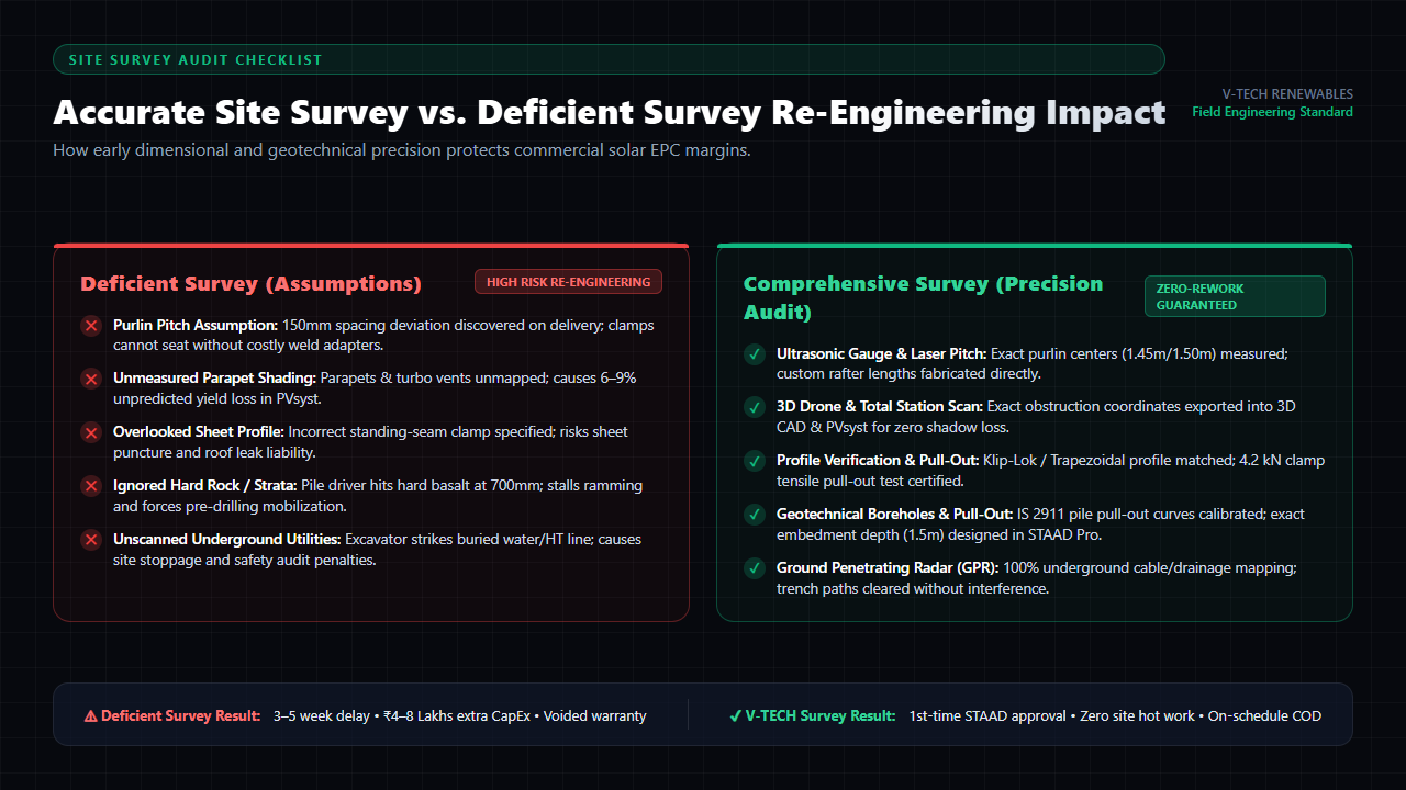
| Site Parameter | Survey Assumption | On-Site Reality & Structural Cost |
|---|---|---|
| Purlin Pitch & Gauge | Assumed uniform 1,500 mm / 2.0 mm | Actual spans vary (1,450–1,680 mm); requires custom clamp fabrication or hot re-welding. |
| Sheet Seam Profile | Generic trapezoidal clamp specified | Proprietary standing seam (e.g., Klip-Lok 700); standard clamps slip or crush sheet ribs. |
| Soil Strata & Refusal | Assumed uniform black cotton soil | Hard basalt strata at 700 mm depth; direct ramming stalls, requiring pneumatic pre-drilling. |
| Roof Obstructions | Skylights and turbo vents ignored | Vents force module layout cutouts; string voltages become unbalanced, causing clipping in PVsyst. |
Field Protocols That Protect Project Margins
Preventing structural revisions requires a strict physical audit before detailed engineering kicks off:
First, deploy 3D drone photogrammetry and total station surveys. A calibrated drone flight generates dense point clouds, exporting true rooftop azimuth, tilt, and obstruction coordinates directly into 3D CAD and PVsyst simulation models. Parapets, cable trays, and HVAC chillers get mapped to the exact centimeter.
Second, verify shed metallurgy and clamp pull-out resistance. Technicians must conduct on-site tensile pull-out tests on sheet seams. A minimum 3.8 to 4.2 kN uplift resistance proves your module mounting structure design will hold during monsoon cyclonic gusts without puncturing industrial profiles.
Third, execute geotechnical boreholes and pile load tests per IS 2911 for ground installations. Knowing exact Soil Bearing Capacity (SBC) and strata depth stops pile-ramming rigs from bending posts against subsurface rock layers.
Early engineering surveys cost a fraction of one emergency site redesign. At V-TECH RENEWABLES, our Design & Engineering team conducts rigorous field audits before finalizing structural calculation sheets. Whether delivering turnkey Solar EPC execution or third-party Quality Assurance audits, we ensure your solar asset clears statutory approvals without re-engineering delays. Also review our guide on Why Incomplete Electrical Drawings Delay Solar Grid Approvals to streamline total project delivery.
Frequently Asked Questions
1. Why do rooftop solar installations fail structural audits after delivery of mounting structures?
Most failures occur because preliminary designs rely on original architectural drawings rather than physical measurements. Variations in purlin spacing (1,450 mm vs 1,650 mm) or reduced purlin gauge (1.6 mm instead of 2.0 mm) invalidate STAAD Pro wind load calculations, forcing site re-engineering.
2. What pull-out test standard is required for ground-mount solar MMS foundations in India?
Pile foundations must undergo vertical uplift and lateral load testing in accordance with IS 2911 (Part 4). Calibrating pile embedment depths against real geotechnical soil bearing capacity prevents foundation pull-out during cyclonic wind events.
3. How does 3D drone photogrammetry improve solar PV layout design?
Calibrated drone surveys export exact point-cloud coordinates of rooftop obstructions like turbo ventilators, parapets, and skylights directly into PVsyst and AutoCAD, eliminating unexpected shadow clipping and row spacing clashes.
About the Author
Written by the Structural & Civil Engineering Team at V-TECH RENEWABLES, Pune—specializing in high-precision solar site surveys, STAAD Pro structural modeling, and geotechnical audits across 500+ MWp of solar installations.